Romilly's HART® and Fieldbus Web Site
HART measurement variables, ranges and status
Copyright © Romilly Bowden 1997.
The primary variable (PV) of a HART measurement device is available both as a digital value, by HART communication, and as an analogue (usually 4-to-20 mA) signal. In fact, there are two representations of the PV in digital form: in engineering units (by Command #1 or Command #3 and others); and as a percent of range (by Command #2). In addition, the actual analogue output current in milliamps can be read by HART Command #3. Every HART message from the field device includes status information, in the form of 8 bits with pre-defined meanings, including two which describe the present state of these various representations of the measurement.
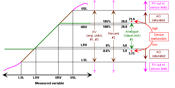
This note attempts to clarify the way in which these representations work when the measurement is out of range, and how this is indicated by the status bits. The preferred effect of a detected device failure on the analogue output is also described (though this is not part of the HART specification). The diagram below gives an overall picture.

First, let's make clear the meanings of the various HART range parameters :
LRV and URV are the Lower Range Value and Upper Range Value, the two values of the PV which are to be represented by 4 mA and 20 mA respectively. You might have called these the "zero" and "full scale" (or possibly "span") of a conventional analogue transmitter (though "span" should really mean the difference between the two). In general terms, this is the "range" of the instrument.
LSL and USL are the Lower Sensor Limit and Upper Sensor Limit. These describe the range over which the sensor works properly. Outside this range, the measurement may be unreliable.
A HART instrument digitises the sensor output over at least the range from the LSL to the USL. (If it doesn't cover the full possible possible range of the sensor, then the range it does cover becomes the LSL and USL for the instrument as a whole.) This digitised value, once it has been converted, corrected, linearised or whatever, becomes the digital form of the PV. That is to say, the digital PV accurately represents the physical measurement over this range: LSL to USL.
Of course, the analogue signal cannot cover this whole range. It accurately represents only the range between the LRV and URV, with a small linear over-range allowance (typically from -0.6% to +105% of range).
It is common practice to indicate a detected device failure by forcing the analogue current value to a value outside the normal range, high or low by user choice, so that a control system can both respond safely, and (if set up with suitable alarm thresholds) can indicate the event to the operator. (This is not part of the HART specification, but is obviously a good idea, even for HART devices, since many hosts only use the analogue signal and do not make use of the HART status information.) For a discussion of this, see "Fault indication in Smart transmitters".
So, looking at the diagram ...
First, notice that the PV in engineering units can be read by commands #1 and #3, and is valid over the whole sensor range, irrespective of the analogue output range. The PV may also give useful (though maybe inaccurate) values beyond this range, or may indicate "not-a-number".
Second, notice that the PV in "percent", read by command #2, is also valid over the whole sensor range, although this may take its value far outside the range 0 to 100%. As a floating point variable, this is no problem. Beyond the sensor range (as for the PV in engineering units), the percent value may continue to be given or may be replaced by "not-a-number".
However, the analogue output itself, and its digital value in milliamps read by command #3, is restricted to the configured analogue output range, plus the small allowable linear over-range from say 3.9 to 20.8 mA. In the event of a device malfunction, both analogue and digital values will be set outside this range, typically at 3.75 or 21.6 mA (depending on the configured choice of down-scale or up-scale fault indication). These are typical values used by a well-known transmitter supplier. NAMUR has recommended slightly different values (see "Fault indication" below).
Now, consider the status indicator bits ...
If the measurement is outside the sensor limits, the "PV out of sensor limits" bit is set.
If the measurement is outside the linear analogue output range (LRV - 0.6% to URV + 5%), the "analogue output saturated" bit is set.
If a failure has been detected, the "device malfunction" bit is set.
Incidentally, it is not usually permitted to set the LRV or URV analogue output range values outside the LSL and USL sensor limits. The LRV can, however, often be set above the URV, to configure a reverse-acting analogue output.
Home Top of page Consultancy